LLDP is a protocol that helps network devices share information about themselves and their connections in a local area network (LAN). It works similarly to a Cisco-specific protocol called CDP. To use LLDP, devices must implement certain data types known as type-length-values (TLVs). The required TLVs include:
Inventory
LLDP-MED capabilities
Network policy
Port VLAN ID
MAC/PHY configuration status
Extended power via media dependent interface (MDI)
LLDP helps management tools, like Simple Network Management Protocol (SNMP), find and fix network problems. It is used with Ethernet, Fiber Distributed Data Interface (FDDI), and token ring media. LLDP Media Endpoint Discovery (MED) was developed for Voice over IP (VoIP) devices. LLDP sends out messages to nearby devices, sharing details like device names, versions, and port information. This allows devices to learn about their neighbors, as these messages are sent and received on all active connections. Additionally, devices can be set to stop sending or receiving information on specific ports.
A network device will only send LLDP messages until it receives an LLDP-MED message from another device. After that, it will continue to send LLDP-MED messages to that device.
Types of Endpoints
LLDP-MED can support different types of devices:
Class 1: Basic devices like IP communication controllers
Class 2: Devices that support streaming media
Class 3: Devices for IP communications, such as VoIP phones
Benefits of LLDP
Now that we know what LLDP is, let’s look at some of its benefits:
Network management can track devices and find out their software and hardware versions.
It automatically discovers local network policies.
It works with devices from different manufacturers.
It supports Management Information Base (MIB) for better management.
It helps locate devices for Enhanced 911 services on VoIP devices.
It manages power for devices that use Power over Ethernet (PoE).
It provides tools to troubleshoot issues like speed and connection problems, and it tells phones which VLAN they should connect to.
LLDP Packet Information
LLDP uses Ethernet to send its messages. The Ethernet type for LLDP is 0x88cc. LLDP Data Units (LLDPDUs) are sent to a special multicast address. Important details in the packet include the destination address, which is the LLDP multicast address, and the type of packet, which is 0x88cc. The packet also shows the MAC address of the sending device, the port being used, and the system name and description.
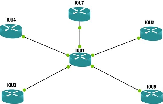
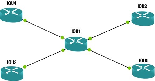
All Cisco devices that use LLDP create a list of information from neighboring devices, which can be viewed using the command show lldp. To activate LLDP, you use the command lldp run. The command show lldp neighbors shows information about devices connected to your router, while show lldp neighbors detail provides more detailed information.
Example Commands
Here are some example commands for enabling LLDP and checking information on a router or switch:
Terminal Console output
Enter configuration commands, one per line. End with CNTL/Z.

IOU1(config)#lldp run
IOU1(config)#exit
IOU1#show lldp ?
This will show options like neighbor entries and statistics. The output will include details about connected devices, such as their capabilities and IP addresses. This information is very useful for troubleshooting connection issues.
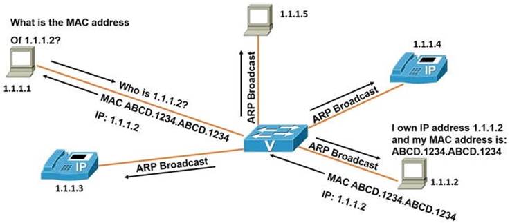
Imagine you’re at a grocery store and can’t find your child. You ask the store manager to make an announcement: “Hi, Bob. Your parent is looking for you. Please come to the front of the store.” This is similar to how ARP works. It sends out a broadcast message that everyone can hear, but only the intended recipient responds. ARP, or Address Resolution Protocol, is used to convert network logical addresses (like IP addresses) into physical hardware addresses (like MAC addresses). Essentially, it translates IP addresses into MAC addresses and stores this information in a device’s ARP table.
When a network device receives a packet with a destination IP address that it owns, but the corresponding MAC address isn’t in its ARP table, it sends out a request to all devices on the network to find out who owns that IP address. The device with the matching IP address replies with its MAC address, and the switch records this information in its ARP table for quicker access in the future.
Here’s an example of how to view the ARP table on a Cisco router:
Terminal Console output
IOU1#show arp

Protocol  Address          Age (min)  Hardware Addr   Type   Interface
Internet  192.168.1.1             0   aabb.cc00.0400  ARPA   Ethernet0/0
Internet  192.168.1.2             -   aabb.cc00.0100  ARPA   Ethernet0/0
Internet  192.168.2.1             0   aabb.cc00.0300  ARPA   Ethernet0/1
Internet  192.168.2.2             -   aabb.cc00.0110  ARPA   Ethernet0/1
Internet  192.168.3.1             0   aabb.cc00.0200  ARPA   Ethernet0/2
Internet  192.168.3.2             -   aabb.cc00.0120  ARPA   Ethernet0/2
Internet  192.168.4.1             0   aabb.cc00.0500  ARPA   Ethernet0/3
Internet  192.168.4.2             -   aabb.cc00.0130  ARPA   Ethernet0/3
The ARP table shows the physical MAC addresses and their corresponding IP addresses. This helps devices quickly send traffic to these IP addresses without needing to broadcast requests each time.
In a typical ARP request scenario, a workstation with the IP address 1.1.1.1 wants to find out the MAC address of the device with the IP address 1.1.1.2. It sends a request to the switch, which then broadcasts an ARP request. The device with IP 1.1.1.2 responds with its MAC address, and the switch records this in its ARP table for future reference, then sends the information back to the requesting workstation.
The Reverse Address Resolution Protocol (RARP)
RARP, or Reverse Address Resolution Protocol, is used to convert physical addresses (MAC addresses) into network layer IP addresses. It works similarly to ARP, but instead of broadcasting an IP address request, it broadcasts a request for an IP address based on a known MAC address. When a device needs to find its IP address but only knows its MAC address, it sends out a RARP request. A device that can map the MAC address to the corresponding IP address will respond with the needed information.
The physical medium, also known as transmission media, refers to how data is transferred across networks. You can think of it like a highway that connects different places, allowing data to travel from one point to another. While transmission media enables data to move from the sender to the receiver, it does not guarantee that the data will arrive. There are two main types of media: solid and wireless. Examples include copper cables and optical fiber. Data can be sent through various types of cables, such as coaxial cables, waveguides, or twisted pair wires.
When data is sent from the sender to the receiver, it is first converted into binary numbers. Then, a carrier signal is adjusted according to the binary data. At the receiving end, this signal is converted back into binary numbers and then decoded. In simple terms, the transmission medium is the path that signals take for data communication. Transmission media can be divided into two categories:
Guided: Data is sent as waves along a solid medium (also called bounded).
Wireless: Data is sent using antennas (also called unbounded).
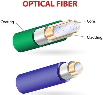
Copper wire is one of the most common types of transmission media used in computer networks. It can carry data over long distances while using low power. Fiber optic cable is another popular medium for long-distance communication. This type of cable is made of thin glass tubes that reflect light to transmit data. Fiber optic cables have advantages over copper wires, such as higher data rates and the ability to transmit data over longer distances without needing repeaters, which can fail. Fiber is also less affected by electromagnetic interference (EMI), making it more reliable.
There are two main types of fiber optic cables:
Multi-mode (MM): This type can be either 62.5 microns or 50 microns in diameter and is used for shorter distances, up to 2 kilometers.
Single-mode (SM): This type has a diameter of 9 microns and is used for longer distances, capable of carrying signals over several kilometers.
Examples of wireless signals include microwave, radio, and infrared.
Types of Transmission
There are three types of transmission methods:
Simplex: Data can only be sent in one direction; one device is the sender and the other is the receiver.
Half-duplex: Both devices can send data, but only one at a time.
Full-duplex: Both devices can send and receive data at the same time.
Network cabling is essential for any network. This section covers different types of cables and their purposes. The main types of transmission media are twisted pair, coaxial, and fiber optic cables. The choice of cabling depends on factors like traffic needs, network layout, cost, maintenance, and network size.
Twisted Pair Cable
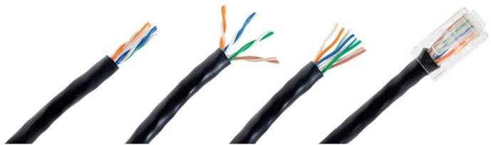
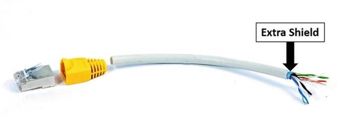
Twisted pair cables consist of two or more pairs of wires twisted together. They are usually less expensive than fiber optic or coaxial cables. An Ethernet cable, for example, has four pairs of twisted wires that are color-coded: blue, brown, green, and orange. Twisted pair cables can connect to registered jack (RJ) connectors or be hardwired to devices. The most common connector today is the RJ45, which is larger than the RJ11 connector used for analog phones. Your laptop or computer typically has an Ethernet port that accepts RJ45 connectors. Each pair of wires includes one solid and one striped wire, with the following color codes:
Blue
White/Blue
Orange
White/Orange
Brown
White/Brown
Green
White/Green
There are two main types of twisted pair cabling:
Unshielded Twisted Pair (UTP): This is the most widely used type of copper cabling in networks today. UTP is relatively inexpensive but does not protect against electrical interference. Its bandwidth is also limited compared to other cables.
Shielded Twisted Pair (STP): This type is used in networks that require faster data rates. STP is similar to UTP but has an extra metal shield around the wires to protect against EMI. The wires can be shielded individually or as a group.
A table of twisted pair category (CAT) ratings shows the maximum data rates they can support and the applications for each category. For example, CAT 5E supports up to 155 Mbps, while CAT 7 can support up to 100 Gbps at 15 meters and 40 Gbps at 50 meters.
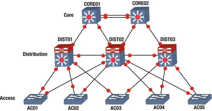
The hierarchical internetwork model, created by Cisco, is a three-layer framework that organizes networks into three distinct layers: core, distribution, and access. Each layer has its own responsibilities for providing services to end devices and servers.
A key aspect of network design is to use switching whenever possible and routing only when necessary. This means that switches should be the primary choice for connecting devices. Another important element is dividing network devices into different zones, which helps separate user access networks from data centers. This separation can be done using routers, switches, or firewalls. Access devices typically connect end devices like VoIP phones, printers, and computers. Networks can be organized by floor or by office.
Core Layer The core layer acts as the backbone of the network and is usually built with high-performance switches and fiber optic cables. This layer does not handle traffic routing to local area networks (LANs) and focuses solely on fast and reliable packet delivery. It is designed with redundancy to ensure continuous operation. The model starts with two core switches that manage switching and routing, allowing for maximum performance through multiple connections to the distribution layer.
Distribution Layer The distribution layer connects to the access layer and is mainly focused on switching. It can connect redundantly to both the core and user switches. To achieve the best performance, uplinks to this layer should also consist of multiple connections. Firewalls and Network Address Translation (NAT) can be set up at this layer. Routing between different VLANs and workgroups occurs here, and devices in this layer need to handle a large amount of traffic. In larger networks, multilayer switches are recommended. Redundancy is also important at this layer, as a failure could impact many users. Devices should have backup connections to access layer devices and redundant power supplies.
Access Layer The access layer, also known as the edge layer, includes hubs and switches that connect client devices to the network. This layer is responsible for ensuring that clients can receive data on their computers and phones. Any device that connects users to the network is considered an access layer device. The architecture of the hierarchical internetwork model developed by Cisco is illustrated in the accompanying figure.
Port numbers are used to identify specific services and applications on a computer. The well-known port numbers range from 0 to 1023 and are typically used by system processes. Overall, port numbers can go from 0 to 65535. When packets arrive at the transport layer, they are directed to the right application by looking at the destination port number. Below is a table of some well-known port numbers for various services.
Before we dive into the OSI model, let’s talk about why it matters. The OSI model is important to understand because it helps you see how different protocols work together and how each layer interacts with the others. Knowing this can help you troubleshoot problems and understand how devices communicate. Even if you think you’ll only work with certain layers, it’s good to know how all the layers function. This knowledge can help you when fixing issues with your devices.
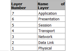
The OSI model, also called the seven-layer model, was created by the International Organization for Standardization (ISO) and the International Telecommunication Union (ITU-T). Its purpose is to create a common way for communication protocols to work together.
It’s important to remember that the OSI model is not a strict rule but a guide for companies to follow so their products can work with each other. The seven layers are:
Application
Presentation
Session
Transport
Network
Data Link
Physical
The OSI model divides communication functions into these seven layers. Each layer supports the one above it and is supported by the one below it. The top three layers (Application, Presentation, and Session) deal with how applications on devices communicate with each other. These devices can be computers, servers, printers, or even smart appliances.
The bottom four layers (Physical, Data Link, Network, and Transport) explain how data is sent from one place to another. These layers are crucial for devices like routers.
Benefits of the OSI Model
Here are some advantages of using the OSI model:
It standardizes the industry and explains what happens at each layer.
By having a standard, many companies can create products that work together.
It breaks down network communication into smaller, simpler parts, making it easier to develop, troubleshoot, and design.
Problems in one layer usually stay in that layer, making it easier to fix issues.
The Application layer connects users with their devices and manages communication between users or hosts. The lower four layers focus on how data travels through physical connections and network devices. The upper three layers don’t deal with networking directly.
Functions of Each Layer
Here’s a simple analogy to explain the functions of each layer in the OSI model, using the example of a CEO sending a letter:
Application (Layer 7): This layer supports user applications. The CEO decides to send a letter to a colleague.
Presentation (Layer 6): This layer translates data. The CEO’s assistant writes down the letter.
Session (Layer 5): This layer manages sessions. The assistant puts the letter in an envelope and gives it to the mailroom, instructing them to send it quickly.
Transport (Layer 4): This layer handles data transfer. The mailroom decides to use a courier for fast delivery and prepares the letter for shipping.
Network (Layer 3): This layer manages routing. The courier adds handling information and plans the best route to deliver the letter.
Data Link (Layer 2): This layer ensures data is framed and addressed correctly. The workers tag the envelope for its destination.
Physical (Layer 1): This layer deals with the actual transmission of data. The plane flies to the destination city.
After the letter reaches its destination, the process continues in reverse, with the layers working together to ensure the letter is delivered correctly.
Now that we understand what each layer does, we will explore each layer in more detail in the following sections.
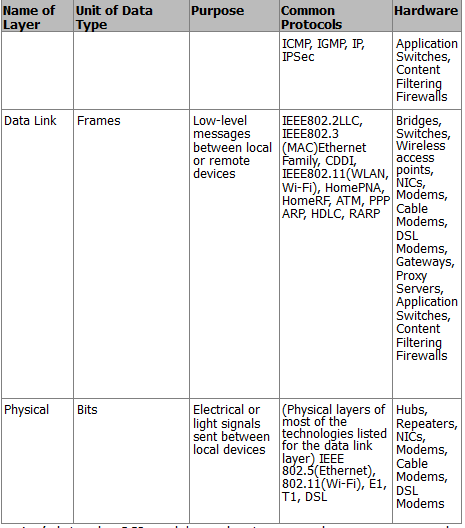
Physical Layer
The physical layer is all about the actual materials used to send data, like air, copper wires, or glass fibers. This layer sets the rules for how to create, maintain, and end a communication channel. In the OSI model, the physical layer takes data frames from the data link layer and turns them into signals, which are just ones and zeros that can be sent through the chosen medium. Different ways to send data include using electromagnetic waves for wireless signals, lasers for fiber optics, and electrical pulses for copper cables like Cat6 Ethernet.
This layer also defines how devices connect to the transmission medium, including details like pin layouts, voltage levels, signal timing, and how far data can travel. To help organize the data being sent, the physical layer uses a synchronization flag or preamble to separate different transmissions. In short, the physical layer focuses on:
The type of medium used for transmission
The energy form used for sending data (like light)
The characteristics of the channel (like whether it can send data in both directions at once)
Data Link Layer
The data link layer helps the network layer above it by managing error handling and flow control. It makes sure messages are sent to devices on a local area network (LAN) using their physical hardware addresses. This layer changes packets from the network layer into frames that can be sent to the physical layer. It adds a header to these frames that includes the source and destination addresses, flow control information, and error-checking data.
When a frame is received, the extra information is removed before sending the message to the network layer. The data link layer only cares about physical addresses, not logical ones. It identifies each device’s unique hardware address on the LAN.
The data link layer has two parts:
Media Access Control (MAC): This part controls how packets are sent over the network. It uses a first-come, first-served method, meaning everyone shares the bandwidth. It also handles error notifications and ensures frames are delivered correctly.
Logical Link Control (LLC): This part checks for errors and makes sure packets are synchronized. It helps the data link layer know how to process packets when they arrive.
When a frame is received, the LLC checks the error data. If everything matches, it sends a signal back to confirm receipt. If not, the sender will resend the frame.
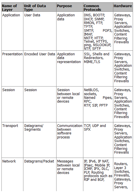
Network Layer
The network layer is responsible for giving devices logical addresses, figuring out where they are on the network, and finding the best path to send packets. Routers operate at this layer and help direct traffic within networks. This layer creates logical paths to send packets from one place to another and translates logical addresses into physical addresses.
A network is made up of many devices that communicate with each other using logical addressing. For example, if a computer with the IP address 192.168.1.1 sends a packet to a router, the router checks if the destination IP address is in its local network. If it’s not, the router forwards the packet to the next router until it reaches its destination.
Transport Layer
The transport layer breaks down data into smaller pieces and puts them back together for the session layer. It provides services to ensure data is sent reliably from one host to another. This layer can create connections that are either reliable (connection-oriented) or fast (connectionless).
Reliable transport ensures that data is sent correctly by using acknowledgments. When a segment of data is received, the receiver sends a confirmation back to the sender. If the sender doesn’t get this confirmation, it will resend the data. This layer also makes sure that data is sent in the right order and helps prevent issues like congestion and data loss.
In a connection-oriented session, a three-way handshake is used to establish a connection before data is sent. This is like having a conversation where both parties agree to communicate. Once the session is done, the connection is closed. Connection-oriented communication is important for tasks like file transfers, while connectionless communication is better for quick tasks like video calls.
Session Layer
The session layer is in charge of starting, managing, and ending sessions between applications that are either on the same device or different ones. It controls how these devices connect and can operate in three ways: full-duplex (both can send and receive at the same time), half-duplex (only one can send or receive at a time), or simplex (one-way communication). This layer keeps the data from different applications separate. When using a connection-oriented mode, it puts data back together as it comes in, while in connectionless mode, it passes data through without changing it. The session layer also makes sure sessions close properly and can create checkpoints to recover data if something goes wrong. It can pick up where it left off if a connection or file transfer is interrupted.
Some examples of the session layer include:
SQL (Structured Query Language): A tool that helps users define what information they need from local and remote systems.
RPC (Remote Procedure Call): A tool that helps different services communicate with each other.
NFS (Network File System): A system that allows access to files on remote computers, working with TCP/IP and UNIX systems.
Presentation Layer
The presentation layer is responsible for changing data into a format that applications can understand. It recognizes the different ways applications use data and packages this data into units that the session layer can use. This ensures that data sent from one application can be read by another application on a different system. If an application uses a special code that isn’t standard, this layer will convert it into a standard format. It also encrypts data for security when sending it over the network and can compress data to make it transfer faster. If the data is encrypted, it can only be decoded by the application on the receiving end.
Some examples of standards in the presentation layer include:
JPEG (Joint Photographic Experts Group): A standard for images.
MPEG (Movie Picture Experts Group): A standard for compressing and coding video.
TIFF (Tagged Image File Format): A format for high-quality images.
RTF (Rich Text Format): A format for sharing text files between different word processors.
Application Layer
The application layer is where programs that send or receive data interact. It supports applications that users work with, like email, Telnet, and file transfer programs. This layer takes care of things like quality of service, user authentication, and privacy since everything is specific to the application being used. For example, when you send an email, your email program uses the application layer to do so.
Some popular applications in the application layer include:
World Wide Web (WWW): A platform that presents various formats, including graphics, text, sound, and video, connecting users to servers.
Email: Uses protocols like SMTP (Simple Mail Transfer Protocol) for sending messages and POP3 (Post Office Protocol version 3) for receiving them between different email applications.
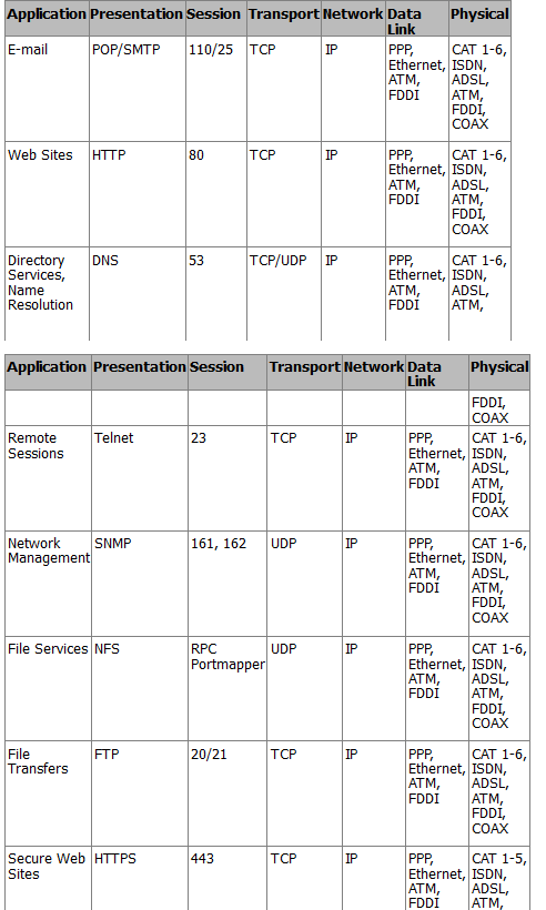
TCP/IP Application Layer
The TCP/IP application layer is where programs communicate with each other. Different protocols can be used here, depending on what the program needs. This layer also sets rules for how users interact with the software.
Some important protocols at this layer include:
FTP (File Transfer Protocol): Used for transferring files.
SMTP (Simple Mail Transfer Protocol): Used for sending email.
HTTP (HyperText Transfer Protocol): Used for web traffic.
This layer connects with the transport layer through ports. The Internet Assigned Numbers Authority (IANA) decides which ports are used for different applications. For example, web traffic usually goes through port 80, email uses port 25, and FTP uses ports 20 and 21. The port number helps the transport protocol understand what type of data is being sent, allowing the right application to receive it.
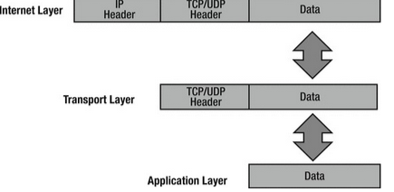
TCP/IP Transport Layer
The TCP/IP transport layer works similarly to the transport layer in the OSI model. It uses two main protocols:
TCP (Transmission Control Protocol): This is connection-oriented, meaning it ensures reliable delivery of data and keeps it intact.
UDP (User Datagram Protocol): This is connectionless, which means it focuses on speed rather than reliability.
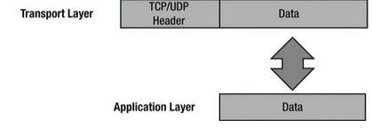
The transport layer takes data from the application layer and breaks it into smaller packets. TCP makes sure these packets arrive in the correct order and sends a signal back to the sender to confirm receipt. If the sender doesn’t get this signal, it will resend the packet. This is why TCP is considered reliable. On the other hand, UDP does not guarantee that packets will arrive in order or even arrive at all, so it’s up to the application to handle any missing packets.
Both TCP and UDP add a header to the data before sending it to the Internet layer. This header includes important information like a checksum to check for errors, source and destination port numbers, and a sequence number for ordering packets.
TCP/IP Internet Layer
The TCP/IP Internet layer is similar to the network layer in the OSI model and is responsible for routing and addressing data. The main protocol used here is the IP (Internet Protocol). This layer gives packets IP addresses and helps route them to different networks.
When packets come from the transport layer, the Internet layer adds source and destination IP addresses before sending them to the network interface layer. The IP address helps direct the packet to its destination. As packets travel, they pass through various routers. You can see how this works by using the command prompt on your computer and typing tracert apress.com to see the path the packet takes.
Some protocols used at the Internet layer include:
IP: This protocol takes data from the transport layer and packages it for the network interface layer. It does not confirm receipt, so it’s considered unreliable.
ICMP (Internet Control Message Protocol): This protocol sends error messages when a host or router cannot be reached.
ARP (Address Resolution Protocol): This protocol maps IP addresses to physical hardware addresses.
RARP (Reverse Address Resolution Protocol): This protocol helps workstations on a local network request their IP address.
The maximum size of data frames sent over a network is called the maximum transfer unit (MTU). For Ethernet networks, the MTU is usually 1,500 bytes. If a network cannot handle this size, the IP protocol can break the data into smaller pieces, which are then reassembled at the destination.
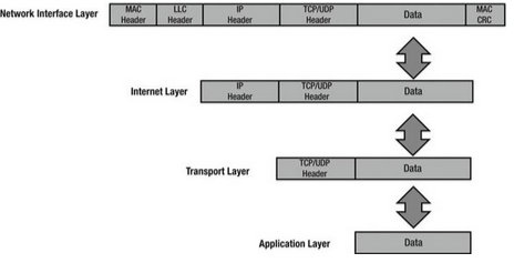
TCP/IP Network Interface Layer
The TCP/IP network interface layer corresponds to the data link and physical layers of the OSI model. It uses physical hardware addresses to send data and defines how data is physically transmitted.
Data packets are sent to the network interface layer to reach their destination. This layer depends on the type of physical connection, like Ethernet or wireless.
The Logical Link Control (LLC) layer adds the protocol used for transmission at the Internet layer, so the receiving end knows how to handle the data. The Media Access Control (MAC) layer is responsible for creating the frame that is sent over the network and includes the source and destination MAC addresses.
When packets arrive at the Internet layer, they are turned into datagrams, and when they reach the network interface layer, they are converted into Ethernet frames before being sent to their destination.