Before we dive into the OSI model, let’s talk about why it matters. The OSI model is important to understand because it helps you see how different protocols work together and how each layer interacts with the others. Knowing this can help you troubleshoot problems and understand how devices communicate. Even if you think you’ll only work with certain layers, it’s good to know how all the layers function. This knowledge can help you when fixing issues with your devices.
The OSI model, also called the seven-layer model, was created by the International Organization for Standardization (ISO) and the International Telecommunication Union (ITU-T). Its purpose is to create a common way for communication protocols to work together.
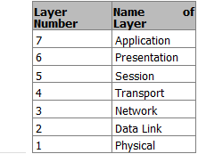
It’s important to remember that the OSI model is not a strict rule but a guide for companies to follow so their products can work with each other. The seven layers are:
- Application
- Presentation
- Session
- Transport
- Network
- Data Link
- Physical
The OSI model divides communication functions into these seven layers. Each layer supports the one above it and is supported by the one below it. The top three layers (Application, Presentation, and Session) deal with how applications on devices communicate with each other. These devices can be computers, servers, printers, or even smart appliances.
The bottom four layers (Physical, Data Link, Network, and Transport) explain how data is sent from one place to another. These layers are crucial for devices like routers.
Benefits of the OSI Model
Here are some advantages of using the OSI model:
- It standardizes the industry and explains what happens at each layer.
- By having a standard, many companies can create products that work together.
- It breaks down network communication into smaller, simpler parts, making it easier to develop, troubleshoot, and design.
- Problems in one layer usually stay in that layer, making it easier to fix issues.
The Application layer connects users with their devices and manages communication between users or hosts. The lower four layers focus on how data travels through physical connections and network devices. The upper three layers don’t deal with networking directly.
Functions of Each Layer
Here’s a simple analogy to explain the functions of each layer in the OSI model, using the example of a CEO sending a letter:
- Application (Layer 7): This layer supports user applications. The CEO decides to send a letter to a colleague.
- Presentation (Layer 6): This layer translates data. The CEO’s assistant writes down the letter.
- Session (Layer 5): This layer manages sessions. The assistant puts the letter in an envelope and gives it to the mailroom, instructing them to send it quickly.
- Transport (Layer 4): This layer handles data transfer. The mailroom decides to use a courier for fast delivery and prepares the letter for shipping.
- Network (Layer 3): This layer manages routing. The courier adds handling information and plans the best route to deliver the letter.
- Data Link (Layer 2): This layer ensures data is framed and addressed correctly. The workers tag the envelope for its destination.
- Physical (Layer 1): This layer deals with the actual transmission of data. The plane flies to the destination city.
After the letter reaches its destination, the process continues in reverse, with the layers working together to ensure the letter is delivered correctly.
Now that we understand what each layer does, we will explore each layer in more detail in the following sections.
Physical Layer
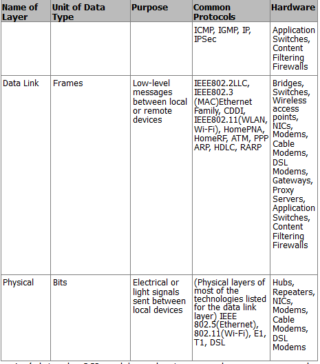
The physical layer is all about the actual materials used to send data, like air, copper wires, or glass fibers. This layer sets the rules for how to create, maintain, and end a communication channel. In the OSI model, the physical layer takes data frames from the data link layer and turns them into signals, which are just ones and zeros that can be sent through the chosen medium. Different ways to send data include using electromagnetic waves for wireless signals, lasers for fiber optics, and electrical pulses for copper cables like Cat6 Ethernet.
This layer also defines how devices connect to the transmission medium, including details like pin layouts, voltage levels, signal timing, and how far data can travel. To help organize the data being sent, the physical layer uses a synchronization flag or preamble to separate different transmissions. In short, the physical layer focuses on:
- The type of medium used for transmission
- The energy form used for sending data (like light)
- The characteristics of the channel (like whether it can send data in both directions at once)
Data Link Layer
The data link layer helps the network layer above it by managing error handling and flow control. It makes sure messages are sent to devices on a local area network (LAN) using their physical hardware addresses. This layer changes packets from the network layer into frames that can be sent to the physical layer. It adds a header to these frames that includes the source and destination addresses, flow control information, and error-checking data.
When a frame is received, the extra information is removed before sending the message to the network layer. The data link layer only cares about physical addresses, not logical ones. It identifies each device’s unique hardware address on the LAN.
The data link layer has two parts:
- Media Access Control (MAC): This part controls how packets are sent over the network. It uses a first-come, first-served method, meaning everyone shares the bandwidth. It also handles error notifications and ensures frames are delivered correctly.
- Logical Link Control (LLC): This part checks for errors and makes sure packets are synchronized. It helps the data link layer know how to process packets when they arrive.
When a frame is received, the LLC checks the error data. If everything matches, it sends a signal back to confirm receipt. If not, the sender will resend the frame.
Network Layer
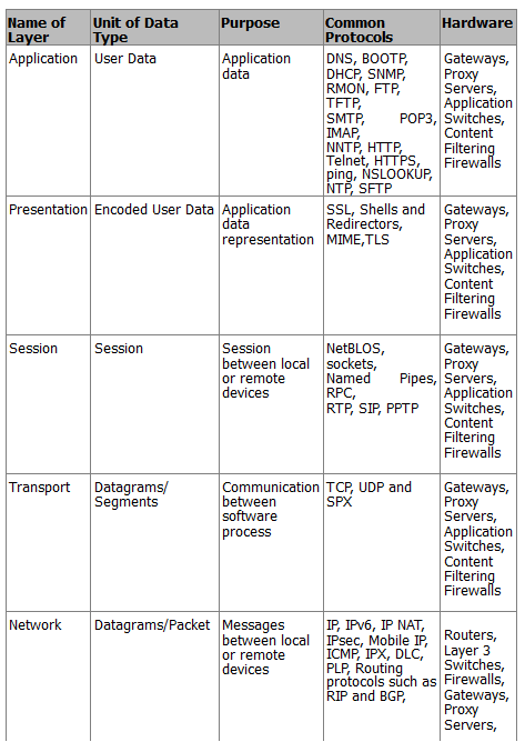
The network layer is responsible for giving devices logical addresses, figuring out where they are on the network, and finding the best path to send packets. Routers operate at this layer and help direct traffic within networks. This layer creates logical paths to send packets from one place to another and translates logical addresses into physical addresses.
A network is made up of many devices that communicate with each other using logical addressing. For example, if a computer with the IP address 192.168.1.1 sends a packet to a router, the router checks if the destination IP address is in its local network. If it’s not, the router forwards the packet to the next router until it reaches its destination.
Transport Layer
The transport layer breaks down data into smaller pieces and puts them back together for the session layer. It provides services to ensure data is sent reliably from one host to another. This layer can create connections that are either reliable (connection-oriented) or fast (connectionless).
Reliable transport ensures that data is sent correctly by using acknowledgments. When a segment of data is received, the receiver sends a confirmation back to the sender. If the sender doesn’t get this confirmation, it will resend the data. This layer also makes sure that data is sent in the right order and helps prevent issues like congestion and data loss.
In a connection-oriented session, a three-way handshake is used to establish a connection before data is sent. This is like having a conversation where both parties agree to communicate. Once the session is done, the connection is closed. Connection-oriented communication is important for tasks like file transfers, while connectionless communication is better for quick tasks like video calls.
Session Layer
The session layer is in charge of starting, managing, and ending sessions between applications that are either on the same device or different ones. It controls how these devices connect and can operate in three ways: full-duplex (both can send and receive at the same time), half-duplex (only one can send or receive at a time), or simplex (one-way communication). This layer keeps the data from different applications separate. When using a connection-oriented mode, it puts data back together as it comes in, while in connectionless mode, it passes data through without changing it. The session layer also makes sure sessions close properly and can create checkpoints to recover data if something goes wrong. It can pick up where it left off if a connection or file transfer is interrupted.
Some examples of the session layer include:
- SQL (Structured Query Language): A tool that helps users define what information they need from local and remote systems.
- RPC (Remote Procedure Call): A tool that helps different services communicate with each other.
- NFS (Network File System): A system that allows access to files on remote computers, working with TCP/IP and UNIX systems.
Presentation Layer
The presentation layer is responsible for changing data into a format that applications can understand. It recognizes the different ways applications use data and packages this data into units that the session layer can use. This ensures that data sent from one application can be read by another application on a different system. If an application uses a special code that isn’t standard, this layer will convert it into a standard format. It also encrypts data for security when sending it over the network and can compress data to make it transfer faster. If the data is encrypted, it can only be decoded by the application on the receiving end.
Some examples of standards in the presentation layer include:
- JPEG (Joint Photographic Experts Group): A standard for images.
- MPEG (Movie Picture Experts Group): A standard for compressing and coding video.
- TIFF (Tagged Image File Format): A format for high-quality images.
- RTF (Rich Text Format): A format for sharing text files between different word processors.
Application Layer
The application layer is where programs that send or receive data interact. It supports applications that users work with, like email, Telnet, and file transfer programs. This layer takes care of things like quality of service, user authentication, and privacy since everything is specific to the application being used. For example, when you send an email, your email program uses the application layer to do so.
Some popular applications in the application layer include:
- World Wide Web (WWW): A platform that presents various formats, including graphics, text, sound, and video, connecting users to servers.
- Email: Uses protocols like SMTP (Simple Mail Transfer Protocol) for sending messages and POP3 (Post Office Protocol version 3) for receiving them between different email applications.
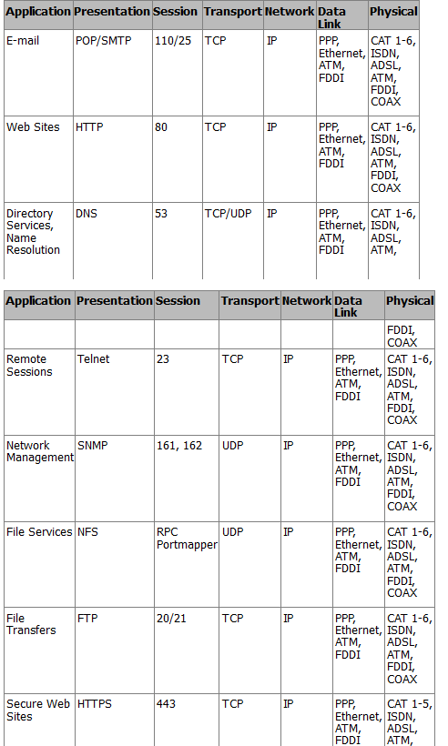
TCP/IP Application Layer
The TCP/IP application layer is where programs communicate with each other. Different protocols can be used here, depending on what the program needs. This layer also sets rules for how users interact with the software.
Some important protocols at this layer include:
- FTP (File Transfer Protocol): Used for transferring files.
- SMTP (Simple Mail Transfer Protocol): Used for sending email.
- HTTP (HyperText Transfer Protocol): Used for web traffic.
This layer connects with the transport layer through ports. The Internet Assigned Numbers Authority (IANA) decides which ports are used for different applications. For example, web traffic usually goes through port 80, email uses port 25, and FTP uses ports 20 and 21. The port number helps the transport protocol understand what type of data is being sent, allowing the right application to receive it.
TCP/IP Transport Layer
The TCP/IP transport layer works similarly to the transport layer in the OSI model. It uses two main protocols:
- TCP (Transmission Control Protocol): This is connection-oriented, meaning it ensures reliable delivery of data and keeps it intact.
- UDP (User Datagram Protocol): This is connectionless, which means it focuses on speed rather than reliability.
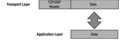
The transport layer takes data from the application layer and breaks it into smaller packets. TCP makes sure these packets arrive in the correct order and sends a signal back to the sender to confirm receipt. If the sender doesn’t get this signal, it will resend the packet. This is why TCP is considered reliable. On the other hand, UDP does not guarantee that packets will arrive in order or even arrive at all, so it’s up to the application to handle any missing packets.
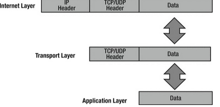
Both TCP and UDP add a header to the data before sending it to the Internet layer. This header includes important information like a checksum to check for errors, source and destination port numbers, and a sequence number for ordering packets.
TCP/IP Internet Layer
The TCP/IP Internet layer is similar to the network layer in the OSI model and is responsible for routing and addressing data. The main protocol used here is the IP (Internet Protocol). This layer gives packets IP addresses and helps route them to different networks.
When packets come from the transport layer, the Internet layer adds source and destination IP addresses before sending them to the network interface layer. The IP address helps direct the packet to its destination. As packets travel, they pass through various routers. You can see how this works by using the command prompt on your computer and typing tracert apress.com to see the path the packet takes.
Some protocols used at the Internet layer include:
- IP: This protocol takes data from the transport layer and packages it for the network interface layer. It does not confirm receipt, so it’s considered unreliable.
- ICMP (Internet Control Message Protocol): This protocol sends error messages when a host or router cannot be reached.
- ARP (Address Resolution Protocol): This protocol maps IP addresses to physical hardware addresses.
- RARP (Reverse Address Resolution Protocol): This protocol helps workstations on a local network request their IP address.
The maximum size of data frames sent over a network is called the maximum transfer unit (MTU). For Ethernet networks, the MTU is usually 1,500 bytes. If a network cannot handle this size, the IP protocol can break the data into smaller pieces, which are then reassembled at the destination.
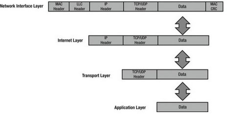
TCP/IP Network Interface Layer
The TCP/IP network interface layer corresponds to the data link and physical layers of the OSI model. It uses physical hardware addresses to send data and defines how data is physically transmitted.
Data packets are sent to the network interface layer to reach their destination. This layer depends on the type of physical connection, like Ethernet or wireless.
The Logical Link Control (LLC) layer adds the protocol used for transmission at the Internet layer, so the receiving end knows how to handle the data. The Media Access Control (MAC) layer is responsible for creating the frame that is sent over the network and includes the source and destination MAC addresses.
When packets arrive at the Internet layer, they are turned into datagrams, and when they reach the network interface layer, they are converted into Ethernet frames before being sent to their destination.